Table Of Contents
Page 15: THE LED FLASHER
Build your own LED FLASHER and learn how it works
This is Project #2 on the PC board in “5-PROJECTS”
To purchase “5 PROJECTS” kit, click HERE.
(you will also need a soldering iron, solder and side-cutters. These are available from your local electronics store)
In this project we flash a Light Emitting Diode (LED). The circuit is exactly the same as in project 1 with two additional components - a 10u electrolytic and a 10n capacitor. The 10u changes the operation of the circuit considerably and it’s handy we covered the operation of the two transistor section in project 1 in so much detail so all we have to describe is the operation of the electrolytic.

The electrolytic is a feedback component and we will see how feedback alters the operation of a circuit.

CONSTRUCTION
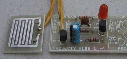
( ) Fit the 10u electrolytic to the board as shown in the diagram with the positive lead going down the hole marked ”+” and the negative lead down the hole next to it.
( ) Fit the 10n capacitor to the holes marked “10n”.
Switch the circuit ON and touch the touch plate lightly. The LED will start to flash and as you press harder, the flash rate will increase.
PARTS LIST
The HIGH GAIN AMPLIFIER must be built first
The extra parts for the LED Flasher:
- 1 - 100k resistor (brown-black-yellow-gold)
- 1 - 10n ceramic capacitor
- 1 - 10u electrolytic
We have already covered the operation of the two transistors and shown how they create a very high gain amplifier. We also explained how the current through the touch plate is amplified thousands of times by the two transistors and the result is sufficient to turn ON the LED.

The addition of the capacitor (the electrolytic comes under the broad heading of capacitors, along with greencap, ceramic, monoblock, polyester, styro, mica and others) turns the circuit ON for a very short period of time then off again, and the cycle repeats.
The LED is actually ON for only a very short period of time and your eyes extend the time considerably. This is one of the tricks used in electronics to save energy. Because it is ON for such a short time, the average current taken by the circuit is very small as it only draws current from the battery in very short bursts.
The only thing we will be describing in this project is the function of the 10u electrolytic.
HOW THE CIRCUIT WORKS
When the battery is connected, both the transistors are off. When you touch the touch plate, current flows through your finger to charge the 10u electrolytic. The 22R and 47k complete the charge path.
When the voltage on the base of Q1 rises to about .6v, the transistor turns ON and its collector-emitter resistance drops. This resistance is in series with a 1k resistor and they form the base-bias resistor for the PNP transistor. You will notice the PNP transistor and its base-bias resistor (the 1k and collector-emitter resistance of Q1) are inverse to the layout of the NPN transistor, so simply think “up-side-down” and you will understand the PNP version. Current passes through the Light Emitting Diode in the emitter of Q2 and it illuminates.
The current also flows through the 22R resistor and when current flows through a resistor, a voltage is developed across it. This voltage appears on the negative lead of the electrolytic and the electro is “raised up.” The positive lead is also raised up by the same amount and the energy that was put into the electrolytic at the beginning of the cycle flows into the base of Q1 to turn it on harder.
When the two transistors turn on harder the brightness of the LED increases. The voltage across the 22R increases and the electrolytic is raised even higher. This process continues to run around the circuit until both transistors are fully turned on and the electrolytic begins to charge in the forward direction via the base of Q1, the collector-emitter leads of Q2 and the LED. This produces the ON time for the LED and as we mentioned in the section on capacitors, the initial charging current for a capacitor is high and it gradually tapers off as the electro becomes charged. This is what happens in this case and when the capacitor is nearly fully charged, the charging current reduces to a point where Q1 is not turned on as much.
This causes Q2 to turn off slightly and the voltage on the positive lead drops a small amount. The negative lead follows and as we learnt in the section on transistors, when the voltage on the base of a transistor falls below .6v, the transistor does not turn on at all.
At this stage in the cycle Q1 turns off more and causes Q2 to turn off also.
A few more decrements and both transistors are fully turned off.
This causes the positive lead of the electrolytic to drop to the level of the negative rail.
The amazing part in this portion of the cycle is the electrolytic is fully charged and since the positive lead drops by about 7v, the negative lead falls by an equivalent amount and so the base of the first transistor sees a negative voltage (-7v!) that keeps it fully turned off.
The charge on the electrolytic is gradually neutralised by current flowing through the touch plate and when all the charge is neutralised, the electrolytic begins to get charged in the opposite direction by the same current. The time this takes produces the OFF time for the LED.
The OFF time is considerably longer than the ON time because the current through the touch plate is much smaller than the current through the transistor and LED when charging the electro.
The electrolytic needs to charge to about .6v before the cycle starts again.
You will notice the electrolytic has been placed in the circuit “around the wrong way,” with the positive lead only 22R away from the negative rail. When the cycle begins, the electro gets charged in the opposite direction to about .6v but later in the cycle it gets charged in the forward direction to about 7v. The electro will accept a small reverse charge without being damaged, provided most of the charging is done in the forward direction.
The operation of the circuit is really quite complex and don’t be surprised if you don’t understand it fully. Future e-books will go over these building blocks again and bring everything into focus.
EXPERIMENTING
The object of these projects is to carry out as much individual experimenting as you can before going on to the next project.
Experiment with different pressures on the touch plate and try other substances such as a slice of fruit or vegetable to see how the conductivity of the each compares with your finger.
You can also try some of the liquids mentioned in Project 1, Question 5, to see how they affect the flash rate.
Later, in Project 5 you will be able to test the liquids again with the Siren Circuit and see how much easier it is to work with an audio output to determine the variations in frequency, rather than watching a changing flash rate.
FITTING THE 100k RESISTOR
The touch plate will be required for Project 5 and once you have carried out all the experiments for this project, it can be removed and replaced with a 100k resistor.
( ) Remove the Touch Plate and leads from the PC board
( ) Fit the 100k (brown-black-yellow-gold) resistor near the Touch Plate symbol.
This will create a fixed flash rate of about one flash per second (1Hz).

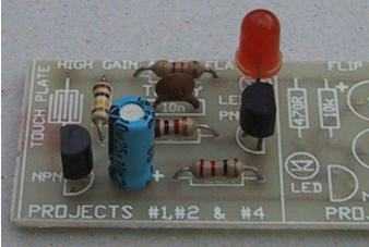
Project 2 with 100k resistor fitted to the board
This completes the second project.
Quick Links
Legal Stuff
Social Media


