Table Of Contents
- CD 4001 Quad NOR gate
- CD 4011 Quad NAND gate
- CD 4013 Dual D Flip Flop
- CD 4014 8-Stage shift register
- CD 4017 Divide by 10
- CD 4020 14-Stage Bin Counter
- CD 4024 7-Stage Binary Count
- CD 4026 7-Segment Driver
- CD 4040 12-Stage Bin Counter
- CD 4049 HEX Inverter
- CD 4060 14-Stage with Osc
- CD 4069 HEX Inverter
- CD 40106 Hex Schmitt Trigger
- CD 4510 BCD up/down Counter
- CD 4511 BCD TO 7-Segment
- LM 324 Quad OP-AMP
- LM 380 4 watt amp
- LM 386 0.5 watt amp
- LM 741 OP-AMP
- OP-AMP List
- Opto Coupler List
- PIC Chip List
- S/mount Diodes/Zeners
- Surface Mount LEDs
- Surface Mount Resistors
- Surface Mount Transistors
- Surface Mount Outlines
- Voltage Regulators
- 40106 Hex Schmitt Trigger
- 555 Timer Chip
- 556 Dual Timer Chip
- 567 Tone Decoder
- 74c14 Hex Schmitt Trigger
There is no recognised circuit symbol for electroluminescence material, however the symbol below is suitable and has been added to our

The way a piece of electroluminescent material gives off light is quite a complex phenomenon and is beyond the scope of this article, but knowledge of the basics will help you understand how a simple project works so you can design your own displays.
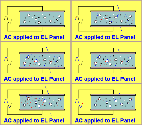
The first thing to understand is how a circuit sees a piece of electroluminescent material. It sees it as a capacitor. The resistance between the two electrodes is almost infinite and thus DC will not pass through it. But when an alternating voltage is applied, the build-up of a charge on the two surfaces, effectively produces a increasing field (called an electric field) and this causes the phosphors within the field to emit light. The increase in voltage in one direction increases the field and this causes a current to flow. The voltage then decreases and rises in the opposite direction. This also causes a current to flow. The net result is a current flows into (commonly thought of as “through”) the electroluminescent panel and thus energy is delivered to the panel. This energy is converted to light via the panel and this conversion is a very efficient process since no heat is produced in the process.
This makes EL a very efficient form of illumination.
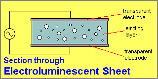
The diagram below is a very simple representation of two electrodes and a thin layer of electroluminescent material sandwiched between.
Note: each electrode is a layer of conducting material. It is so thin that light is able to pass through and be emitted to the surroundings.


Watch the sinewave
Note: light output occurs during both the positive and negative voltages.
Electroluminescent ”wire” or ”cable” is constructed with a thick, stiff, inner wire surrounded by a coating of light-emitting phosphors and around this is wrapped a very fine outer wire. An outer clear plastic jacket or sheath protects the chemicals and insulates the voltages on the wire from external leakage. A cut-away view is shown below:

Electroluminescent material comes in both sheet and wire (cable) varieties. The actual construction of these products is more complex that shown above. The outer wire touches an extremely thin conducting film to produce the outer electrode so an “electric field” will be produced between the inner and outer wires.
For our discussion you can see two wires (electrodes) are present and these must be connected to a voltage source of approx 100v AC. The term AC actually means Alternating Current but it also refers to a voltage that is alternating. We use the term AC to refer to an alternating voltage source. Electroluminescent material will only give off light when an oscillating (alternating voltage) is supplied to it. It does not work on DC (DC is the voltage supplied by a battery).
HISTORY
Electroluminescence was invented in 1936 by G. Destriau when he discovered phosphors, such as copper- or manganese- doped zinc sulphide, glow when subjected to a high voltage field (typically 10,000V/cm). Original EL phosphors were deposited on glass plates. This made them very rigid, thick and delicate. Panels are now thin, flexible, plastic sheets, and can be created in almost any size and shape.
It is possible to purchase a large sheet and cut it into the desired shape. This is only recommended for experimental work or for emergency repair situations as two problems are encountered when doing this.
Firstly, the sheet must have terminating strips so you can connect to the panel, secondly, cutting the sheet produces a raw edge that can “flash-over” and produce sparks. Sometimes you can clean up the edge with the sharp knife to increase the path between the electrodes and thus reduce the occurrence of sparking. This sparking detracts considerably from the energy delivered to the panel and if the sparking produces a “track,” all the energy will be lost in the “short-circuit” and the panel will reduce in brightness or fade out completely.
Once you know how to check the edge for sparking, cutting a sheet to a special shape is the first stage of developing a project.
Remember, the final sheet will have a 0.5cm border of non-illumination, to allow for the sealing between the two layers.
Sheets can also be made with more than one colour and although the layers cannot be placed on top of one another, they can be laid in strips so that a number of effects can be produced.
If three different phosphors are placed side-by-side, the final illumination is less than 33% as compared with a single colour. In addition, the cost of terminating the strips of colour is quite high.
CHANGING THE COLOUR PRODUCED BY EL
The colour produced by an EL panel can be altered by changing the frequency of the voltage supplied to it and/or the amplitude of the voltage.
The change is much greater with some colours. You need to experiment to see the effect. Some panels have almost no visible shift at all. It all depends on who manufactured the panel, its size and the type of inverter.
Quick Links
Legal Stuff
Social Media


