Table Of Contents
Experiments
Page2
REMINDER: These are the items you need for these experiments:
- the 5x7 Display Project with the first row of LEDs (or fully built),
- a 6v battery,
- an interface cable (the components come with the kit)
- a computer.
The project must be tested for wiring faults, faulty LEDs and correct operation, before carrying out any experiments. Always be pleased that something has to be tested or something doesn’t work, because that is the only time when you will LEARN.
The way the author learned electronics is by fixing 35,000 television sets. The way you will LEARN is by fixing a “bug.” The project can be tested by going to the test pages:
The first 6 experiments are on: ”Experiments Page1“.
The next set of experiments use the whole screen and as we have said in the introduction, the screen is scanned from left to right via the 4017 chip. This means each column of LEDs is on for only a very short period of time and you eye has a short retention that merges the images into one. It’s the same as a movie screen or TV screen. They all rely on the eye creating a smooth image from a number of rapidly appearing images.
With our screen, the reason why the columns have to be scanned is due to the 7 rows of information coming from the left-hand-side. If you want to produce the letter “A” on the screen, each column has different LEDs illuminated. If the rows were not scanned, each row would show the information from the first row. By scanning you get enormous flexibility.
Start thinking up your own ideas for games and displays because these experiments are going to give you the “building blocks” for putting your ideas “on the screen.”
The way to start is by modifying one line of code in one of the experiments and seeing what happens. Only change one thing at a time as you may make a mistake and the program will fail to assemble. With each change you will be able to see the result and this will add to your library of knowledge.
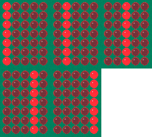
EXPERIMENT-7 COLUMN SHIFT RIGHT
This experiment shifts a column of LED from left to right. (It is not the same as Test4 - we have not introduced the principle of scanning with a “ghost” display in memory.) The program turns on all the lines of port6 and output them to the display while a Delay is executed. The port is turned off (to prevent mirroring) and the 4017 is clocked to the next output. The cycle is repeated for the 5 columns and the program repeats by going to “Shift.”
Experiment-7 for “5x7 Display” Project
;PIC16F84 and only F84 chip
;Column shift right
Start   ORG 0x00
        BSF 03,5    ;Go to page1 to set the ports
        MOVLW 00h   ;Put 00 into W
        MOVWF 05h   ;Make all RA lines output
        MOVWF 06h   ;Make all RB lines output
        BCF 03,5    ;Go to Page0 for programming

Shift   MOVLW 05
        MOVWF 19h   ;Put 5 in the Count file for 5 columns
        BSF 05h,1   ;Reset 4017
        BCF 05h,1   ;allow 4017 to clock via clock line

Shift1  MOVLW 7F
        MOVWF 06h   ;Turn on 7 outputs for LEDs
        CALL Delay
        MOVLW 00    ;Turn off LEDs to prevent mirroring
        MOVWF 06h
        CALL Clock  ;Clock the 4017
        DECFSZ 19h,1   ;Decrement the count file
        GOTO Shift1
        GOTO Shift

Clock   BCF 05,0    ;Clock the 4017
        NOP
        BSF 05,0
        RETURN

Delay   MOVLW 03
        MOVWF 1Ah
Delay1  DECFSZ 1Bh,1
        GOTO Delay1
        DECFSZ 1Ch,1
        GOTO Delay1
        DECFSZ 1Ah,1
        GOTO Delay1
        RETURN

    END

The block of numbers below is the HEX file for Experiment-7. Copy and paste it into a text program such as TEXTPAD or NOTEPAD and call it: Expt-7.hex
:100000008316003085008600831205309900851420
:1000100085107F3086001620003086001220990B54
:1000200009280528051000000514080003309A006F
:0E0030009B0B18289C0B18289A0B1828080008
:00000001FF
EXPERIMENT-8 COLUMN SHIFT-RIGHT/LEFT
The experiment moves a column of LEDs across the display then back again. Moving the column back is not as easy as moving forward as the 4017 only clock from left to right. To move the column to the left, the 4017 has to be reset (so you know the first output is HIGH) then clocked so that the fourth output is HIGH. The LEDs can then be turned ON. This is repeated by clocking the 4017 two times to produce the third column and finally once to produce the second column, before the program goes to “Shift.”
Experiment-8 for “5x7 Display” Project
;PIC16F84 and only F84 chip
;Column of LEDs moves across and back
Start   ORG 0x00
        BSF 03,5    ;Go to page1 for setting-up the ports
        MOVLW 00h   ;Put 00 into W
        MOVWF 05h   ;Make all RA lines output
        MOVWF 06h   ;Make all RB lines output
        BCF 03,5    ;Go to Page0 for programming

Shift   MOVLW 05
        MOVWF 19h   ;Put 5 in the Count file for 5 columns
        BSF 05h,1   ;Reset 4017
        BCF 05h,1   ;allow 4017 to clock via clock line

Shift1  MOVLW 7F
        MOVWF 06h   ;Turn on 7 outputs for LEDs
        CALL Delay
        MOVLW 00    ;Turn off LEDs to prevent mirroring
        MOVWF 06h
        CALL Clock  ;Clock the 4017
        DECFSZ 19h,1  ;Decrement the count file
        GOTO Shift1

        MOVLW 03h
        MOVWF 19h   ;3 shifts - yes 3 shifts!
AAA     CALL Back
        DECFSZ 19h,1
        GOTO AAA
        GOTO Shift

Back    BSF 05h,1
        BCF 05h,1   ;Reset 4017 and allow 4017 to clock
        MOVLW 00h
        MOVWF 06h   ;Turn off LEDs to prevent "streaking"
        MOVF 19h,0  ;Copy 19h into W
        MOVWF 18h   ;Copy W into file 18h
BBB     CALL Clock
        DECFSZ 18h,1
        GOTO BBB
        MOVLW 7Fh
        MOVWF 06h   ;Turn on all 7 LEDs
        CALL Delay
        RETURN

Clock   BCF 05,0    ;Clock the 4017
        NOP
        BSF 05,0
        RETURN

Delay   MOVLW 03
        MOVWF 1Ah
Delay1  DECFSZ 1Bh,1
        GOTO Delay1
        DECFSZ 1Ch,1
        GOTO Delay1
        DECFSZ 1Ah,1
        GOTO Delay1
        RETURN

     END

The block of numbers below is the HEX file for Experiment-8. Copy and paste it into a text program such as TEXTPAD or NOTEPAD and call it: Expt-8.hex
:100000008316003085008600831205309900851420
:1000100085107F3086002820003086002420990B30
:100020000928033099001720990B132805288514F7
:10003000851000308600190898002420980B1D2890
:100040007F308600282008000510000005140800F5
:1000500003309A009B0B2A289C0B2A289A0B2A28EB
:02006000080096
:00000001FF
EXPERIMENT-9 ACROSS/BACK-UP/DOWN
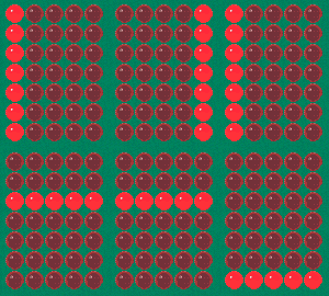
This experiment moves a column of LEDs across the screen and back again. It then moves a row of LEDs up the screen and down. This then repeats. The program shows the number of steps required to produce the effects and you will notice the row of LEDs is not as bright as the column. The reason is the row of LEDs are scanned and the energy that normally goes into one LED has to be divided by 5 LEDs. Even though each LED is receiving one one-fifth of the normal energy, its brightness is not reduced too much due to the nature of the solid-state device.
Experiment-9 for “5x7 Display” Project
;PIC16F84 and only F84 chip
;Column of LEDs moves across/back then up and down
 Start  ORG 0x00
        BSF 03,5    ;Go to page1 for setting-up the ports
        MOVLW 00h   ;Put 00 into W
        MOVWF 05h   ;Make all RA lines output
        MOVWF 06h   ;Make all RB lines output
        BCF 03,5    ;Go to Page0 for programming
        GOTO Main

Back    BSF 05h,1
        BCF 05h,1   ;Reset 4017 and allow 4017 to clock
        MOVLW 00h
        MOVWF 06h   ;Turn off LEDs to prevent "streaking"
        MOVF 19h,0  ;Copy 19h into W
        MOVWF 18h   ;Copy W into file 18h
Back1   CALL Clock
        DECFSZ 18h,1
        GOTO Back1
        MOVLW 7Fh
        MOVWF 06h   ;Turn on all 7 LEDs
        CALL Delay
        RETURN


Scan    MOVLW 080h  ;Determines the number of scans before
        MOVWF 1Ch   ;incrementing routine
Scan1   BSF 05h,1   ;Reset 4017
        BCF 05h,1   ;allow 4017 to clock via clock line
        MOVLW 05h
        MOVWF 19h   ;File 19h counts the number of columns

Scan2   CALL Short
        BCF 05,0    ;Clock the 4017
        BSF 05,0
        DECFSZ 19h,1
        GOTO Scan2
        DECFSZ 1Ch,1
        GOTO Scan1
        RETURN


Clock   BCF 05,0    ;Clock the 4017
        NOP
        BSF 05,0
        RETURN

Delay   MOVLW 03
        MOVWF 1Ah
Delay1  DECFSZ 1Bh,1
        GOTO Delay1
        DECFSZ 1Ch,1
        GOTO Delay1
        DECFSZ 1Ah,1
        GOTO Delay1
        RETURN

     ;Short Delay

Short   DECFSZ 1Bh,1
        GOTO Short
        RETURN

   ;Moves a column of LEDs across the screen and back,
   ;then up and down the screen

Main    MOVLW 05
        MOVWF 19h    ;Put 5 in the Count file for 5   columns
        BSF 05h,1    ;Reset 4017
        BCF 05h,1    ;allow 4017 to clock via clock line
Main1   MOVLW 7F
        MOVWF 06h     ;Turn on 7 outputs for LEDs
        CALL Delay
        MOVLW 00      ;Turn off LEDs to prevent mirroring
        MOVWF 06h
        CALL Clock    ;Clock the 4017
        DECFSZ 19h,1  ;Decrement the count file
        GOTO Main1
        MOVLW 03h
        MOVWF 19h     ;3 shifts - yes 3 shifts!
Main2   CALL Back
        DECFSZ 19h,1
        GOTO Main2
        BSF 05h,1
        BCF 05h,1     ;Reset 4017
        CALL Delay    ;This illuminates the first row!
        MOVLW 01
        MOVWF 06h     ;Turn on first LED
        BCF 03h,0     ;clear the carry flag
Main3   CALL Scan
        RLF 06,1
        BTFSS 06,7    ;When 8th! output is HIGH, program repeats
        GOTO Main3
        MOVLW 20h
        MOVWF 06h
Main4   CALL Scan
        RRF 06,1
        BTFSS 06,0
        GOTO Main4
        CALL Scan     ;This illuminates bottom row!
        GOTO Main

  END

The block of numbers below is the HEX file for Experiment-9. Copy and paste it into a text program such as TEXTPAD or NOTEPAD and call it: Expt-9.hex
:100000008316003085008600831231288514851000
:1000100000308600190898002120980B0C287F30AA
:1000200086002520080080309C008514851005304E
:1000300099002E2005100514990B19289C0B1528E2
:100040000800051000000514080003309A009B0BFF
:1000500027289C0B27289A0B272808009B0B2E2863
:10006000080005309900851485107F308600252012
:10007000003086002120990B352803309900062096
:10008000990B3F2885148510252001308600031028
:100090001320860D861F4828203086001320860CEA
:0800A000061C4E281320312834
:00000001FF
Go to the next page of experiments: 5x7 EXPERIMENTS: Page-3
Quick Links
Legal Stuff
Social Media


